Flash Type ADC is based on the principle of comparing analog input voltage with a set of reference voltages.
To convert the analog input voltage into a digital signal of n-bit output, (2n – 1) comparators are required.
The following figure shows 2- bit flash type ADC
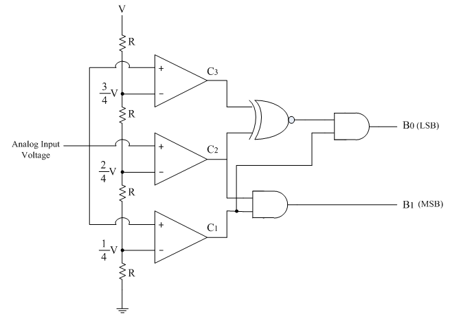
The three op-amps are used as comparators. The non-inverting inputs of all the three comparators are connected to the analog input voltage. The inverting terminals are connected to a set of reference voltages (V/4), (2V/4) and (3V/4) respectively which are obtained using a resistive divider network and power supply +V.
The output of the comparator is in positive saturation(i.e. logic 1), when voltage at non-inverting terminal is greater than voltage at inverting terminal and is in negative saturation otherwise.
The following table shows the comparator outputs for different ranges of analog input voltages and their corresponding digital outputs.
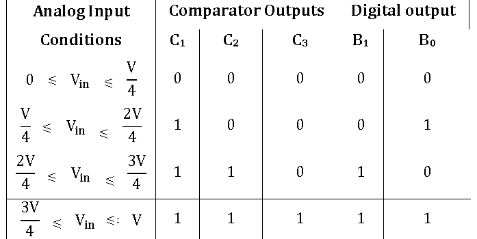
Consider first condition, where analog input voltage VA is less than (V/4). In this case, the voltage at the non-inverting terminals of all the three comparators is less than the respective voltages at inverting terminals and hence the comparator outputs are C1C2C3 = 000.
This comparator outputs are applied to the further coding circuit to get the digital outputs as B1B0 = 00
Similarly the digital outputs are calculated for other three conditions also.
Advantages:
1)It is the fastest type of ADC because the conversion is performed simultaneously through a set of comparators, hence referred as flash type ADC. Typical conversion time is 100ns or less.
2)The construction is simple and easier to design.
Disadvantages:
1)It is not suitable for higher number of bits.
2)To convert the analog input voltage into a digital signal of n-bit output, (2n – 1) comparators are required. The number of comparators required doubles for each added bit.