Home > analog integrated circuits > current to voltage converter
Current to voltage converter
In this case the input current is converted into a proportional voltage. Therefore we can have
Vo∠Iin
∴Vo=S Iin
Where, S→Constant of proportionality which is nothing but the Sensitivity of current to voltage converter.
The sensitivity S is given as the ratio of output voltage to input current, which is nothing but a trans- resistance and hence this circuit is also called as trans-resistance amplifier.
∴S =Vo/Iin
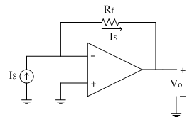
Consider the following circuit as shown below.

Here input applied is a current source 'Is'. Since input current to the op-amp is zero, same current flows through the feedback resistor Rf.
From the figure,
Vo=-IS * Rf
∴ Vo∠IS
Here the sensitivity is S=-Rf
Thus the output voltage is proportional to input current. This type of circuit is more useful for finding small currents of the order of 2µA (eg. Photo-diode current).
Such a small amount of currents are not possible to measure practically. In such type of circuits the output voltage is measured first with the help of digital multi-meter and then from the equation below the current is calculated
IS=(-Vo)/Rf
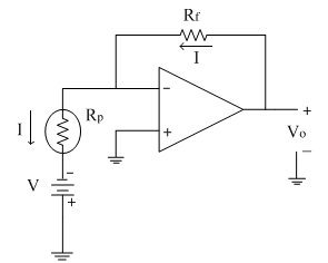
High Sensitivity I to V converter:
As explained for the above mentioned circuit, the sensitivity is S=-R_f. The sensitivity of the above circuit can be increased by increasing the feedback resistance. Thus the feedback loop is modified with a resistive 'T' section as shown below.
The input current Iin is allowed to flow through the resistance R; because input current to op-amp is zero. Assume the voltage 'V' as shown in diagram above. The input current divides at node 'V' to have currents I1 and I2 as shown.
Applying KCL at node 'V'
Iin=I1+I2
Substituting for the currents
(0-V)/R=(V-0)/R1 +(V-Vo)/R2
(-V)/R=V/R1 +V/R2 -Vo/R2
Vo/R2 =V[1/R+1/R1 +1/R2 ]
∴Vo =VR2 [1/R+1/R1 +1/R2 ]
∴Vo =V[R2/R+R2/R1 +1]
But node voltage 'V' is, V=-Iin R
∴Vo =-Iin S
Thus ∴ Vo∠Iin
Applications of current to voltage Converters:
1) Photodiode Current measurement:
One of the major applications of current to voltage converter is photo detector amplifier as shown below.

The photodiode is operated in reverse bias condition. The voltage 'V' is applied to it.
From the circuit diagram,
Vo=ID Rf
∴ Vo∠ID
The diode current is calculated as follows
ID=Vo/Rf
ID is the photodiode current proportional to the intensity of light incident on it. This current is input current to the circuit and is calculated as given in equation above.
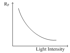
2) Measurement of Photo resistor:
This type of circuits is used to measure the photo resistor as shown in circuit diagram below.
In dark condition, the resistance is very large. As the intensity of light incident on photodiode is increased, the resistance decreases as shown in graph below.
As mentioned in above application, first the output voltage is measured on DMM. From the equation of output we have
Vo=IRf
This equation is used to calculate current 'I' as
I= Vo/Rf
The current flowing through the photo resistor is also given by equation
I= V/RP
∴RP=V/I
Thus from the above equation photo-resistor RP is calculated.
Current scaler/ Current amplifier:
The following circuit diagram shows a basic current amplifier. It is also called as current scaler.
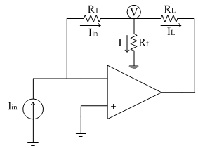
As shown in the figure, the input applied is a current source Iin. The non-inverting terminal is kept at ground potential. A resistive 'T' section is formed in the feedback path as shown in figure above.
Due to virtual ground concept, the inverting terminal appears to be at ground potenstial. Consider the potential 'V' as shown in the figure.
Applying KCL at the node 'V'
Iin=I+IL
∴IL=Iin-I……..(1)
The input current is given as
Iin=(0-V)/R1 =-V/R1 …….(2)
The current 'I' is given as
I= (V-0)/Rf =V/Rf
∴V=IRf
Substitute the value of 'V' in equation (2), we get
I=-[R1/Rf ] Iin
Substituting this current 'I' in equation (1), we get
∴IL=Iin+[R1/Rf ] Iin
∴IL=[1+R1/Rf ] Iin
Where, [1+R1/Rf ] =≫gain of the amplifier/scaling factor
Thus by proper selection of R1 and Rf, the input current can be scaled to the required level at the output.