Home > mini projects > Audio Amplifier circuit with noise filtering
Audio Amplifier circuit with noise filtering
Abstract This project gives an insight into the practical use of audio amplifier along with a noise filtering circuit. Any random signal given to input containing any noise can be filtered using the noise filtering circuit and then provided to the audio amplifier for amplification of the inputted signal. An audio amplifier is an electronic device that increases the strength (amplitude) of audio signals that pass through it. An audio amplifier amplifies low-power audio signals to a level which is suitable for driving loudspeakers. In several practical circuits using op amps we observe the noise present in the output waveform. This results in an undesired output waveform. Thus majority of the circuits require audio amplifiers along with a noise filtering circuit.
I. INTRODUCTION1
An amplifier's job is to turn a small electric current into a larger one, and there are numerous ways to achieve this depending on exactly what you're trying to do. Noise is random electrical activity which may (or may not) have some frequency dependent components. The addition of noise to a desired electrical signal shows itself differently in the digital arena vs the analog arena. For the digital world, all digital inputs have a voltage threshold below which the signal is interpreted as zero, and above which in interpreted as one. If the noise level comes close to this threshold, then the inputs will be erroneously interpreted. Some inputs have schmitt triggers as part of the input circuitry to reduce this error. In analog circuits, the presence of noise is harder to avoid, as there is no innate thresholding. Consequently, noise manifests as errors which tend to remove information from the signal - i.e. it masks off parts of the signal which would otherwise carry useful data. The parts that are obscured tend to be low amplitude or high frequency signals, but this is dependent on the kind of noise that is being encountered. Thus, to avoid such issues in real time conditions we necessarily require to use and audio amplifier circuit along with a noise filtering circuit.
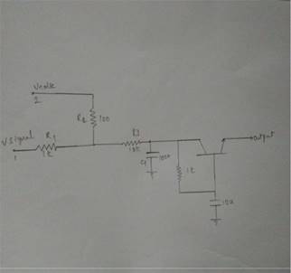
This audio noise filter circuit is a bandpass filter for audio frequency band. It filters unwanted signals that are lower or higher than the audio frequencies. It has 2 filters: a low pass filter and a high pass filter in a cascade configuration. Practically in microphones, speakers, loudspeaker or audio systems we have audio amplifiers. Interference is one of the main problem in such devices. There are lots of devices that emit radio waves. If those radio waves are on the same frequency as your sound system and speakers, you could get some garbled signals as you listen to your music. We also notice noisy signals in the output waveforms of these circuits. Thus, a noise filtering circuit is used in such conditions to avoid the noise problems. Since these circuits(microphones, loudspeakers, speakers and audio system) are used in everyday purposes it is highly recommended to use audio amplifiers along with noise filtering circuits for such devices hence providing us with much desirable and better signal.
2. AUDIO AMPLFIER BASICS
Any electronic device that increases the power of an electrical signal whose vibrations are confined to the audio frequency range- the range that can be perceived by the human ear-is an audio amplifier. All devices that transmit, record or otherwise electronically process voice signals employ audio amplifiers. Amplification of the signal produced by a microphone-often termed preamplification-is necessary because the electrical signal that can be derived directly from sound waves impinging on a microphone is weak (i.e., on the order of 0.1V or less). Input signal of such low amplitude must be amplified before they can be processed in either analog or digital circuits. The number of audio amplifier designs that have been produced over the last century is probably in the hundreds of thousands. Such devices are a ubiquitous feature of modern life, and are found in computers, telephones, radios, high-fidelity audio systems, all military voice-communication systems, many appliances, and even toys.
Audio amplifiers can be miniaturized for placement in headsets, mobile phones. In applications where small size is at a premium, as in hearing aids and espionage applications (bugs and "wires"), they may be ultraminiaturized.
3. NOISE FILTERING CIRCUIT BASICS
Noise is defined as a high-frequency electrical distortion of the voltage waveform. It is comprised of unwanted and interfering voltages and currents generated by motors, office equipment, industrial equipment, etc.
White noise is a common source of electronic noise in circuitry and is also called Johnson noise or thermal noise. It is caused by the collisions of the charge carriers in circuitry e.g. electrons, and the noise power is proportional to absolute temperature - hence the term thermal noise. This thermal dependence is also the reason why circuitry is sometimes cooled down - e.g. in cameras for astronomy.
Thus, a low pass filter can be used to suppress noise and obtain a better output waveform. a low-pass filter is a circuit offering easy passage to low-frequency signals and difficult passage to high-frequency signals. There are two basic kinds of circuits capable of accomplishing this objective, and many variations of each one: The inductive low-pass filter and the capacitive low-pass filter. The inductor's impedance increases with increasing frequency. This high impedance in series tends to block high-frequency signals from getting to the load.
The capacitor's impedance decreases with increasing frequency. This low impedance in parallel with the load resistance tends to short out high-frequency signals, dropping most of the voltage across series resistor R1.
The inductive low-pass filter is the pinnacle of simplicity, with only one component comprising the filter. The capacitive version of this filter is not that much more complex, with only a resistor and capacitor needed for operation. However, despite their increased complexity, capacitive filter designs are generally preferred over inductive because capacitors tend to be "purer" reactive components than inductors and therefore are more predictable in their behavior. By "pure" it is meant that capacitors exhibit little resistive effects than inductors, making them almost 100% reactive. Inductors, on the other hand, typically exhibit significant dissipative (resistor-like) effects, both in the long lengths of wire used to make them, and in the magnetic losses of the core material. Capacitors also tend to participate less in "coupling" effects with other components (generate and/or receive interference from other components via mutual electric or magnetic fields) than inductors and are less expensive.
II. ADVATAGES OF THE CIRCUIT
I.) Transmission of original signal without much loss of the original information.
II.) Removal of white noise and higher frequency components.
III.) More accurate representation of sound can be done in analog amplifier circuits.
III. DISADVANTAGES OF THE CIRCUIT
I.) Because of the use of analog circuits there is usage of more bandwidth than digital circuits.
II.) Harder to synchronize analog sounds
III.) Power dissipation is more compared to digital circuits.
CODE IN NGSPICE
*project*
.include opamp.cir
.model bjt1 npn
.model bjt2 pnp
Vsig 1 0 sin(0 5v 2.5k)
Vnoise 2 0 dc 0 trnoise(200m 5m 0 0)
R1 3 1 1k
R2 3 2 100
R3 4 3 10k
C1 4 0 100n
Q1 4 5 6 bjt1
R4 5 4 1k
C2 5 0 10u
R5 7 6 10k
xop1 8 7 9 amp
R6 10 7 270k
C3 10 7 50p
R7 8 0 47k
R8 9 0 470k
C4 10 9 0.01u
Q2 10 14 15 bjt2
Q3 10 16 14 bjt2
R9 15 16 1k
V1 15 0 dc 12V
Q4 10 17 18 bjt1
Q5 10 18 19 bjt1
R10 19 17 1k
V2 19 0 dc -12V
R11 10 0 1meg
xop2 10 11 12 amp
R12 11 0 10
R13 12 11 10meg
.control
tran .5m 400m
run
set color0=white
set color1=black
set xbrushwidth=3
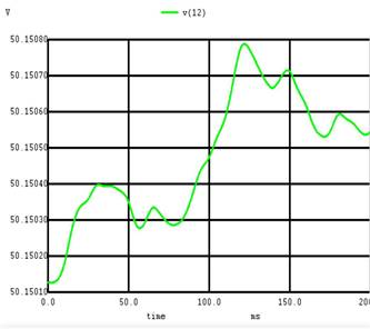
plot v(12)
plot v(10)
plot v(3)
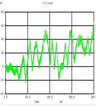
plot v(4) v(6)
.endc
.end
Op amp subcircuit
:
*OP AMP*
.subckt amp 1 2 6
R1 1 2 10Meg
R2 3 4 1K
C1 4 0 15U
R3 5 6 10
E1 3 0 1 2 100K
E2 5 0 4 0 1
.ends
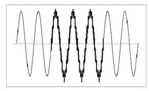
INPUT WAVEFORM(WITH NOISE):