Home > mini projects > Short Range radio Transmitter and Receiver
Short Range radio Transmitter and Receiver
ABSTRACT
In this project, we implement a radio transmitter and receiver that makes use of amplitude modulation for the transmission of the given speech signal. The frequency of the carrier has been adjusted as 600KHz and the message signal transmitted is in the human voice frequency range.
INTRODUCTION
Modulation refers to the technique in which modification of any parameter of a carrier wave is done, in accordance to the amplitude of the signal to be transmitted. The earliest form of modulation is amplitude modulation, in which the amplitude of the carrier wave is varied with the amplitude of the data signal. This broadcasting technique is currently used in the transmission of spoken-word formats such as talk radio, news etcetera. AM, when compared to other modulation techniques such as FM and PM, is more susceptible to interference and has limited audio fidelity and hence, it finds applications in transmission of speech signals.
MATHEMATICAL ANALYSIS
An amplitude modulated wave typically consists of a sinusoidal carrier wave, that lies in the radio frequency range, from 535KHz to 1600KHz. The data signal to be transmitted is superimposed on this carrier wave as follows:
m(t)= Amcos(2Ï€fmt), is the message signal.
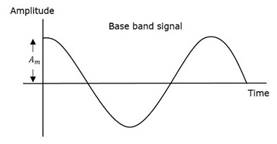
Fig. Carrier wave
Here, Ac and Am are respectively the amplitudes of the carrier and the message signals and fc and fm are their respective frequencies. The modulated wave is represented in the form,
s(t)=Ac[1+μcos(2πfmt)]cos(2πfct),
where µ is known as the modulation index, which refers to variation of the modulated variable of the carrier with respect to the unmodulated level. In this case, the modulated variable is the amplitude of the carrier and the modulation index is represented as
µ=Am/Ac
It is also represented as
µ=Amax-Amin/Amax+Amin
where Amax and Amin are the maximum and minimum amplitudes in the modulated wave.
If a modulated wave has a value of µ<1, the signal is called an under-modulated wave.
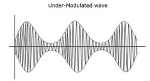
Fig. Message signal
A value of µ>1 produces an over-modulated wave that causes interference and ultimately, loss of information and hence, the value of µ should always be maintained less than one.
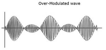
Fig. Over-modulated wave ( µ>1) tracing of the signal.
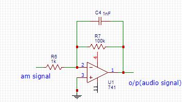
Fig. Demodulator circuit
MODULATOR CIRCUIT
The modulator used for the experiment is known as an emitter modulator ,which makes use of bipolar junction transistors for modulating the input signal. It operates in class A mode but the output obtained is small in magnitude and hence, it cannot be implemented for applications that require high range transmission.
One of the biggest advantages of an emitter modulator is that it is simple to construct and require very low power for operating.
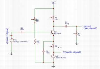
Fig. Emitter modulator
The input signal applied is a sinusoidal wave of frequency 250Hz and the carrier used is of frequency 600KHz.
DEMODULATOR CIRCUIT
Envelope detector is the simplest demodulator for amplitude modulated signals. The trace the boundaries of the modulated wave to generate the message signal. Here, for the demodulation of the modulated wave, an op-amp integrator with a diode at the output has been used, which acts as the envelope detector. Suitable values of resistance R and capacitance C have to be selected in order to have effective
BANDWIDTH
Bandwidth is defined as the size or width of the frequency ranges occupied by a signal. The bandwidth is given by the relation:
B.W= fmax-fmin
where fmax and fmin are the maximum and minimum frequency components in the modulated signal. From the mathematical expression of the modulated wave, the maximum and minimum frequencies can be found out to be
fmax= fc + fm and
fmin= fc - fm
Therefore, bandwidth= 2fm. In the experiment, the bandwidth required would be in the range 170Hz to 510Hz.
CONCLUSION
The radio transmission system built makes use of the most primitive form of modulation i.e. AM modulation for transmission of audio signals and hence, the range that could be covered by the system is low. Also, the data that can be transmitted using this system is confined to human speech signals, due to the limited noise fidelity of the system.