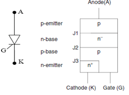
Thyristors are usually three-terminal devices that have four layers of alternating p-type and n-type material. A silicon-controlled rectifier (or semiconductor-controlled rectifier) is a solid state current controlling device. The control terminal of the thyristor, called the gate (G) electrode, connected to an integrated and complex structure as a part of the device. The other two terminals, called the anode (A) and cathode (K), handle the large applied power and conduct the major current through the thyristor.
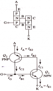
The anode and cathode terminals are connected in series with the load to which power is to be controlled. The Silicon Control Rectifier (SCR) consists of four layers of semiconductors, which form NPNP or PNP structures. It has three junctions, labeled J1, J2, and J3 and three terminals. The anode terminal of an SCR is connected to the P-Type material of a PNPN structure, and the cathode terminal is connected to the N-Type layer, while the gate of the Silicon Control Rectifier SCR is connected to the P-Type material nearest to the cathode. The PNPN thyristor can be considered as two transistors Q1 & Q2 connected in cascade mode. Q1 & Q2 are NPN & PNP transistor such that collector of Q1 connected to the base of Q2. The gate terminal & collector terminal of Q2 connected to the base of Q1. When small gate current is supplied to the base of Q1 the amplified collector current generates very large collector current of Q2. this current is supplied to base of Q1 thus positive feedback is initiated and within a few microseconds saturation is immediately reach. The current is only limited by external load connected with transistor Anode current is directly proportional to Gate Current.
Application of SCR:
1) Controlled Rectifiers
2) DC To Dc Converters
3) DC To AC Converters
4) Battery Chargers
5) Lamp Dimmers
6) AC Voltage Stabilizers
7) Speed Control of AC & DC Motors
- Characteristics of Thyristor
- Gate Characteristics of Thyristor
- Ratings of Thyristor
- Thyristor Commutation
- Thyristor Commutation Techniques
- Triggering Circuit of Thyristor

