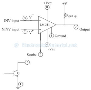
Features of IC comparator:
1) Faster switching between two output levels.
2) Built in noise immunity.
3) Output is capable of directly driving the digital circuits.
4) Strobe function for selection in wired or multiple comparator structures.
5) Output latching facility.
IC LM 311 is operated from dual power supply of ±15 V. It can also be operated from single power supply of +5V when pin number 4 is grounded.
Pin number 1 is externally grounded as a common point for the whole circuit; but in some of the applications we can connect some voltage levels at pin number 1. Transistor is connected at output to drive variety of loads.
Operation:
I) If V^- >V^+, then pin number '7' is internally shorted with pin number'1'. Between pin no. 1 and pin no 7, there is a transistor. In above condition, the transistor goes into saturation and voltage drop across it is nearly zero. Thus pin no 1 is shorted with pin no 7.
II) If V^- <V^+, then output assumes open collector state i.e. no voltage present at pin no 7. In this case we have to attach externally pull-up resistor Rp and a positive voltage +V. As output is open circuited, output voltage at pin no 7 is +V.
Normally +V = +5V for TTL family.
Pin no. 6 is either open circuited or connected to a positive supply. If grounded through a resistor, output assumes open collector state irrespective of input voltage (always open circuit).
Typical Application:
The following figure shows a typical application of IC comparator. The non-inverting terminal is grounded. The sine wave input is applied to inverting terminal. Pin no 6 is open circuited and pin no 1 is shorted to ground.
In positive half cycle of input signal
V^- >V^+
∴Vo=0 [Pin no 1 and pin no 7 shorted to ground.]
In negative half cycle of input signal
V^- < V^+
∴Vo=+V [Open collector state.]

