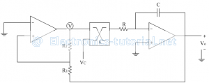
The main function of the VCO is to generate an output frequency that is directly proportional to the input voltage.
This VCO provides simultaneous square wave and triangular wave outputs as a function of the input voltage. The frequency of oscillation is determined by the resistor R and capacitor C along with the voltage V_c applied to the control terminal.
Comparator as a VCO:
The frequency of oscillation can be controlled by external voltage called controlled voltage Vc as shown below.
To change the frequency a multiplier block is added. Generally a multiplier IC AD 533 is used. The IC is having a multiplying factor of K (typically 1/10)
The output of the multiplier IC is = KVsat Vc
Input to the integrator= KVsat Vc
= (Vsat Vc)/10
The total time T is
T=2t1
∴T= (4VT RC)/(Vsat (Vc/10) )
Now, VT/Vsat =R1/Rf
∴T=(40R1 RC)/(Vc Rf )
The frequency of oscillations
f= (Rf Vc)/(40R1 RC)
Thus the output frequency depends on the control voltage Vc. By varying Vc output frequency can be changed.
