Inductor is the component that resists the change of current flowing through it. This resists in the inductor is possible because of the self-induced electromotive force generated in the inductor which results in change in the magnetic field. In electronic circuits when the emf is induced in the circuit where current is changing that effect is known as self-induction. This phenomenon is also called as the back-emf. If this kind of emf is generated adjacently within the magnetic field, then this kind of emf is generated because of the mutual induction. The mutual induction is the working principle of the transformers, motors, relays etc. Self inductance can be considered as the one of the special case of mutual inductance. As we know that, the inductance is measured in Henry, ( H ). However, another unit of inductance is Webers per Ampere. Therefore, ( 1 H = 1 Wb/A ).
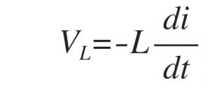
According to Lenz's law, the induced emf produces the current in the direction which resists the change in flux and therefore causes the emf. Hence, in a conducting coil which has an inductance, ( L ) of one Henry, ( 1H ) is available when the electrical current passed in the coil changes at a rate of one ampere/second, ( A/s ) and induces the voltage of one volt. This voltage induced in a coil, ( VL ) with an inductance of L Henries is given by,
In above equation the negative sign shows that, the voltage induced opposes the change in current through the coil per unit time. where: L is the inductance in Henries, VL is the voltage across the coil and di/dt is the rate of change of current in Amperes per second.
As we know that, inductors store the energy in magnetic field form and the inductors are made up of wires which produces the loops within the coil. By increasing the number of loops in the coil, coil inductance increases.
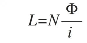
Therefore, the equation of self inductance in terms of coil turns is given by,
Self Inductance of a Coil
Where:
L is in Henries, N is the Number of Turns, F is the Magnetic Flux Linkage and ? is in Amperes

