Definition: A sequential logic circuit is one whose outputs depend not only on its current inputs, but also on the past sequence of inputs.
Combinational versus Sequential Logic
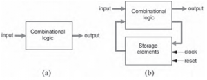
A combinational logic circuit is one in which the outputs depend solely on the current inputs. Thus the system is memory less and has no feedback loops, as in the model of Figure (a) below. In contrast, a sequential logic circuit is one in which the outputs do depend on previous system states, so storage elements are necessary, as well as a clock signal that is responsible for controlling the system evolution. In this case, the system can be modeled as in Figure (b), where a feedback loop, containing the storage elements, can be observed.
The storage capability in sequential circuits is normally achieved by means of flip-flops.
One Bit Memory Cell
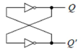
The simplest sequential circuit or storage element is a bistable multivibrator, which is constructed with two inverters connected sequentially in a loop as shown in Figure below. It has no inputs and two outputs labeled Q and Q'. Since the circuit has no inputs, we cannot change the values of Q and Q'. However, Q will take on whatever value it happens to be when the circuit is first powered up.
Assume that Q = 0 when we switch on the power. Since Q is also the input to the bottom inverter, Q', therefore, is a 1. A 1 going to the input of the top inverter will produce a 0 at the output Q, which is what we started off with. Similarly, if we start the circuit with Q= 1, we will get Q' = 0, and again we get a stable situation. A bistable element has memory in the sense that it can remember the state of the circuit indefinitely. Using the signal Q as the state variable to describe the state of the circuit, we can say that the circuit has two stable states: Q= 0, and Q'= 1; hence the name “bistable.” Hence we can say that the bistable circuit can store one bit information in it so called as one bit memory cell.
Latches and Flip-Flops
Latches and flip-flops are the basic elements for storing information. One latch or flip-flop can store one bit of information. The main difference between latches and flip-flops is that for latches, their outputs are constantly affected by their inputs as long as the enable signal is asserted. In other words, when they are enabled, their content changes immediately when their inputs change. Flip-flops, on the other hand, have their content change only either at the rising or falling edge of the enable signal. This enable signal is usually the controlling clock signal. After the rising or falling edge of the clock, the flip-flop content remains constant even if the input changes. There are basically four main types of latches and flip-flops: SR, D, JK, and T. The major differences in these flip-flop types are the number of inputs they have and how they change state.
Clock Signal:
Memory element with clock. Flip-flops are memory elements that change state on clock signals. Clock is usually a square wave. 
-
Two types of triggering/activation:
- pulse-triggered
- edge-triggered
1.Pulse-triggered
- latches
- ON = 1, OFF = 0
2.Edge-triggered
- flip-flops are always edge triggered.
- positive edge-triggered (ON = from 0 to 1; OFF = other time)
- negative edge-triggered (ON = from 1 to 0; OFF = other time)
Other related topics in this Category
- Asynchronous counter
- Counters
- D Flip Flop to JK Flip Flop
- D Flip Flop to SR Flip Flop
- D Flip-flop
- Flip-Flop Excitation Table
- JK Flip Flop to D Flip Flop
- JK Flip Flop to SR Flip Flop Conversion
- JK Flip Flop to T Flip Flop
- JK Flip-Flop – Electronics Tutorials
- Parallel-in to Parallel-out (PIPO) Shift Register
- Parallel-in to Serial-out (PISO) Shift Register
- Serial-in to Parallel-out (SIPO) Shift Register
- Serial-in to Serial-out (SISO) Shift Register
- Shift Registers
- SR Flip Flop to D Flip Flop
- SR Flip Flop to JK Flip Flop Conversion
- SR Flip-flop Electronics Tutorial
- Synchronous counter
- Toggle Flip-flop

