In synchronous counters, the clock input is connected to all of the flip-flops so that they are clocked simultaneously. The term synchronous refers to events that have a fixed time
relationship with each other.
Ring Counters
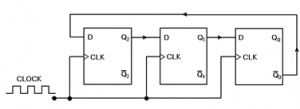
Ring counters are implemented using shift registers. It is essentially a circulating shift register connected so that the last flip-flop shifts its value into the first flip-flop. There is usually only a single 1 circulating in the register, as long as clock pulses are applied.
In the diagram above, assuming a starting state of Q3 = 1 and Q2 = Q1 = Q0 = 0. At the first pulse, the 1 shifts from Q3 to Q2 and the counter is in the 0100 state. The next pulse produces the 0010 state and the third, 0001. At the fourth pulse, the 1 at Q0 is transferred back to Q3, resulting in the 1000 state, which is the initial state. Subsequent pulses will cause the sequence to repeat, hence the name ring counter.
The ring counter above functions as a MOD-4 counter since it has four distinct states and each flip-flop output waveform has a frequency equal to one-fourth of the clock frequency. A ring counter can be constructed for any MOD number. A MOD-N ring counter will require N flip-flops connected in the arrangement as the diagram above.
A ring counter requires more flip-flops than a binary counter for the same MOD number. For example, a MOD-8 ring counter requires 8 flip-flops while a MOD-8 binary counter only requires 3 (23 = 8). So if a ring counter is less efficient in the use of flip-flops than a binary counter, why do we still need ring counters? One main reason is because ring counters are much easier to decode. In fact, ring counters can be decoded without the use of logic gates. The decoding signal is obtained at the output of its corresponding flip-flop.
For the ring counter to operate properly, it must start with only one flip-flop in the 1 state and all the others at 0. Since it is not possible to expect the counter to come up to this state when power is first applied to the circuit, it is necessary to preset the counter to the required starting state before the clock pulses are applied. One way to do this is to apply a pulse to the PRESET input of one of the flip-flops and the CLEAR inputs of all the others. This will place a single 1 in the ring counter.
Johnson/Twisted-Ring Counters
The Johnson counter, also known as the twisted-ring counter, is exactly the same as the ring counter except that the inverted output of the last flip-flop is connected to the input of the first flip-flop.
The Johnson counter works in the following way : Take the initial state of the counter to be 000. On the first clock pulse, the inverse of the last flip-flop will be fed into the first flip-flop, producing the state 100. On the second clock pulse, since the last flip-flop is still at level 0, another 1 will be fed into the first flip-flop, giving the state 110. On the third clock pulse, the state 111 is produced. On the fourth clock pulse, the inverse of the last flip-flop, now a 0, will be shifted to the first flip-flop, giving the state 011. On the fifth and sixth clock pulse, using the same reasoning, we will get the states 001 and 000, which is the initial state again. Hence, this Johnson counter has six distinct states : 000, 100, 110, 111, 011 and 001, and the sequence is repeated so long as there is input pulse. Thus this is a MOD-6 Johnson counter.
The MOD number of a Johnson counter is twice the number of flip-flops. In the example above, three flip-flops were used to create the MOD-6 Johnson counter. So for a given MOD number, a Johnson counter requires only half the number of flip-flops needed for a ring counter. However, a Johnson counter requires decoding gates whereas a ring counter doesn’t. As with the binary counter, one logic gate (AND gate) is required to decode each state, but with the Johnson counter, each gate requires only two inputs, regardless of the number of flip-flops in the counter. Note that we are comparing with the binary counter using the speed up technique discussed above. The reason for this is that for each state, two of the N flip-flops used will be in a unique combination of states. In the example above, the combination Q2 = Q1 = 0 occurs only once in the counting sequence, at the count of 0. The state 010 does not occur. Thus, an AND gate with inputs (not Q2) and (not Q2) can be used to decode for this state. The same characteristic is shared by all the other states in the sequence.
A Johnson counters represent a middle ground between ring counters and binary counters. A Johnson counter requires fewer flip-flops than a ring counter but generally more than a binary counter; it has more decoding circuitry than a ring counter but less than a binary counter. Thus, it sometimes represents a logical choice for certain applications.

